Bucket elevators, Persian wheels and Norias
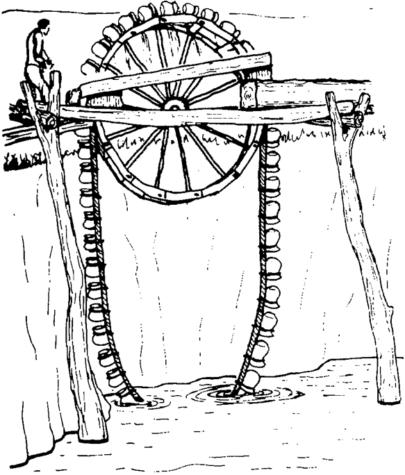
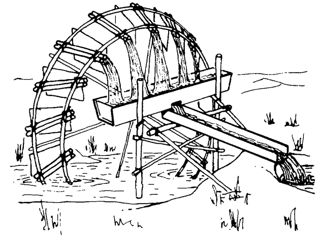
An obvious improvement to the simple rope and bucket is to fit numerous small buckets around the periphery of an endless belt to form a continuous bucket elevator. The original version of this, which is ancient in origin but still widely used, was known as a "Persian wheel"; the earliest forms consisted of earthenware pots roped in a chain which is hung over a drive wheel. The water powered "noria", a water wheel with pots, buckets or hollow bamboo containers set around its rim, is similar in principle except the containers are physically attached to the drive wheel circumference rather than to an endless belt suspended from it.
The flow with any of these devices is a function of the volume of each bucket and the speed at which the buckets pass across the top of the wheel and tip their contents into a trough set inside the wheel to catch the output from the buckets. Therefore, for a given power source and speed of operation roughly the same number of containers are needed regardless of head. In other words, a higher head Persian wheel requires the buckets to be proportionately more spaced out; double the head and you more or less need to double the spacing.
Although Persian wheels and norias are mechanically quite efficient, the main source of loss from these types of device is that some water is spilled from the buckets and also there is a certain amount of friction drag caused when the buckets scoop up water, which again reduces efficiency. Also, the Persian wheel is obliged to lift the water at least 1 m (or more) higher than necessary before discharging it into a trough, which can significantly increase the pumping head, particularly in the case of low lifts. The traditional wooden Persian wheels also inevitably need to be quite large in diameter to accommodate a large enough collection trough to catch most of the water spilling from the pots; this in turn requires a large well diameter which increases the cost.
Improved Persian wheel, (Zawaffa or Jhallar)
Traditional wooden Persian wheels were fitted with earthenware water containers, but a variety of all-metal improved Persian wheels have been built, some as commercial products, in China, India, Pakistan and Egypt. Metal Persian wheels can be made smaller in diameter, which reduces the extra height the water needs to be lifted before it is tipped out of the containers, and also reduces the well diameter that is necessary.
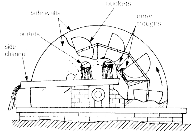
A modified version of the Persian wheel used in Syria and also in Egypt (where it is called the zawaffa or jhallar) includes internal buckets within the drive wheel which catch the water and direct it through holes in the side plate near the hub into a collection trough. This reduces both splashing and spillage losses and the extra height above the collection channel at which the water is tipped. Roberts & Singh gave figures for a modernised metal Persian wheel, of 153m3/h lifted through 0.75m. This implies that efficiencies as high as 75% are possible with modernised devices, which are rather good.
Animal powered
Some performance figures for animal powered Persian wheels:
| Height lifted | Discharge |
|---|---|
| 9m | 8-10m3/h |
| 6m | 10-12m3/h |
| 3m | 15-17m3/h |
| 1.5m | 20-22m3/h |
Depending on the assumption used for the power of the animals in the above examples, the implication is that the efficiency is in the order of 50% at medium lifts such as 6m and perhaps marginally better at higher lifts but worse at lower lifts.
Contents
Suitable conditions
The Persian wheel has been, and still is, widely used particularly in the north of the Indian sub-continent, while the noria was widely used in China, S.E. Asia and to some extent in the Middle East and being normally water powered. Both devices are tending to be replaced by more modern mechanical water lifting techniques as they are old-fashioned and low in output. It should be noted that the term "Persian wheel" is sometimes used to describe other types of animal powered rotary pumps.
The water-powered noria uses the same principle as the Persian wheel and therefore also needs to be of larger diameter than the pumping head, which either limits it to very low lift pumping or requires very large, cumbersome and expensive construction. Small, low-lift norias, used in Thailand and China, are very inexpensive while much larger norias are used in Vietnam and Syria. Some of the largest in Syria exceed 10m in diameter, but in relation to their size they tend to be unproductive compared with more modern pumping systems.
Construction, operations and maintenance
Assembling a water wheel
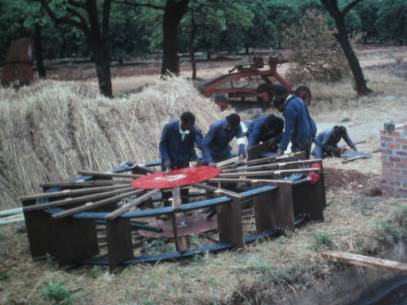
- Parts of the wheel were first made up in the Blair Laboratories. They were then taken to the irrigation canal at Mazowe and assembled. The wheel was made up mostly of plywood and pine beams. The axle was made from 75mm steel pipe, reduced through reducing sockets to 50mm pipe. The axle was mounted through two sealed ball bearings mounted on the two brick built supports at the side of the canal.
- Wheel upright and spiral tube fitted. About 35 meters of 50mm polyethylene pipe were coiled on each side of the pump. The pipes were threaded through holes made in the paddles. The two water collectors were made of 150mm PVC pipe, each about one metre long. The ends of the innermost coils were connected to the axle through polyethylene elbows.
- Straddling the canal. The brick mounts for the bearings had already been made.
- The wheel is mounted. Note the two pipes from the coils going into the axle. This method of linking the pipes to the hollow axle with a galvanised steel cross was not successful. The threads in the pipe were weak points and could not take the strain under the weight of the wheel. The axle was replaced with a single 75mm steel pipe and the water was led into it through an entry point nearer the bearing.
- A drum was mounted on an eight metre platform high above the canal. Water and air coming from the coils was led from the axle, through a simple water seal to the vertical pipe which led to the drum. This photo shows the modified water entry point into the axle, to one side.
Reference manuals, videos, and links
Acknowledgements
- REVIEW OF PUMPS AND WATER LIFTING TECHNIQUES. Natural Resources Management and Environment Department, Food and Agriculture Organization (FAO).


